Electronics: KiCad PCB fabrication and the cap-fun project
I’ve been meaning to look into PCB fabrication forever, and it’s time, baby.
What would I make for my first small PCB? I settled on designing an educational demo board for capacitors. I call it cap-fun.
Capacitor demo boards are nothing new, but I’ve remixed things a little because the usual designs hide some nuances of capacitors that I think can be easily demonstrated.
A typical capacitor demo circuit looks something like this:
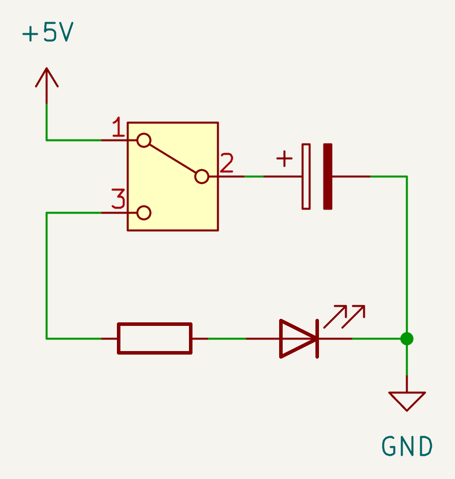
In the shown position the switch is letting the capacitor charge (and the LED is off). In the other switch position the capacitor discharges through the LED, lighting it. The LED fades as the cap runs down.
This demo circuit glosses over the fact that if a capacitor is disconnected from everything, it will just sit there and hold its charge.1
This circuit also skirts around the concept of a cap taking some appreciable time to charge; since there’s no charging resistor before the cap, it will charge pretty much instantly.
This ‘instant charging’ of the cap is potentially a circuit integrity issue. A toy circuit like this could potentially have a transient inrush current of 5 - 10A!
Usually you would notice nothing of this transient high current, but in theory it could stress mechanical parts like USB or battery connectors.
We can address these points and make a more learnable capacitor demo if we use two momentary switches and add a charging resistor. Here’s the schematic for cap-fun:
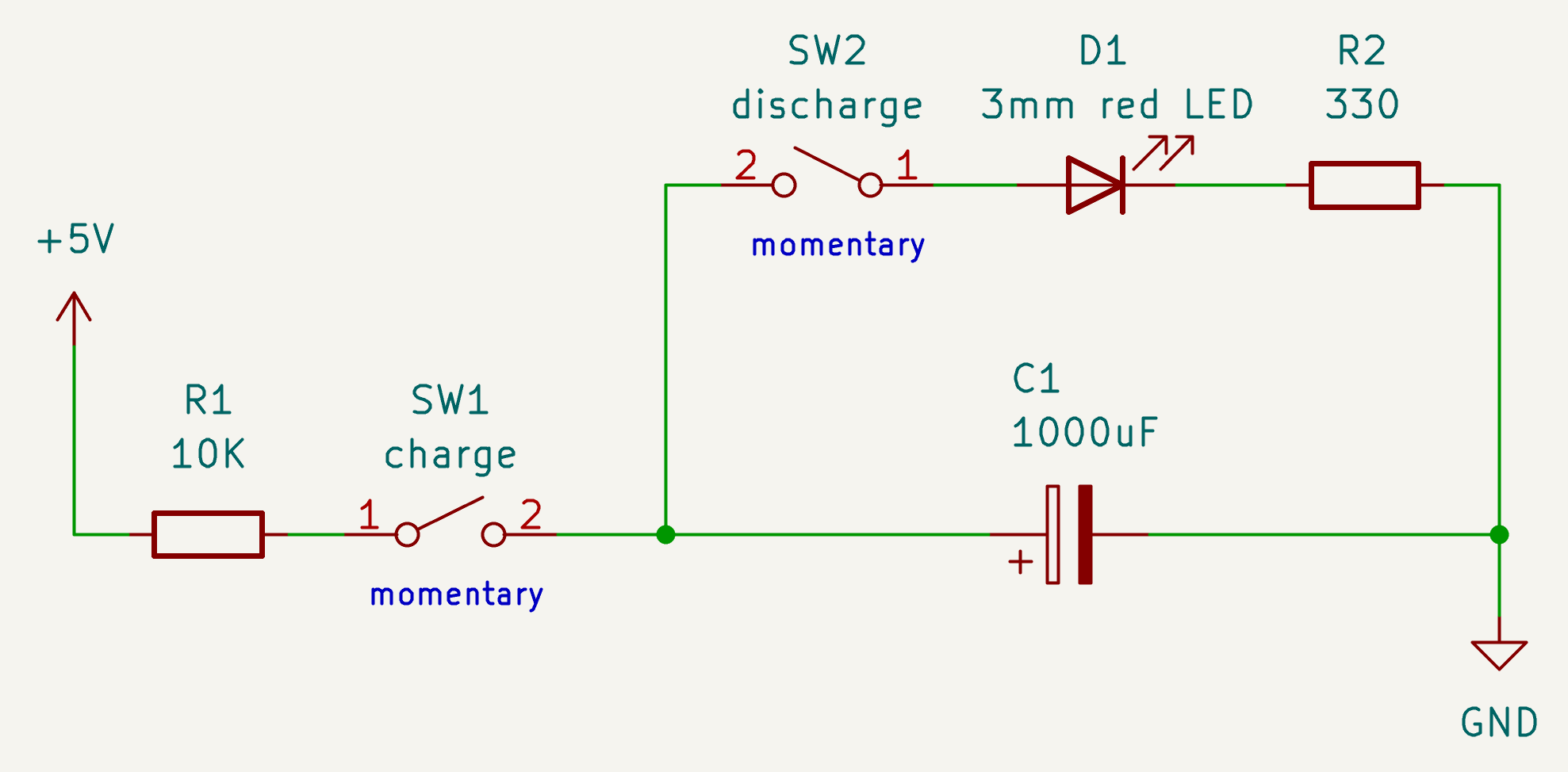
It works as follows:
- with neither switch pressed, the circuit does nothing. Any charge in the capacitor remains there
- with the
chargeswitch pressed, LED is off and capacitor is charging for as long as the button is pressed - with the
dischargeswitch pressed, the capacitor is discharging through the LED, lighting it up with brightness proportionally to the voltage across the cap (and the LED fades over time) - with both buttons pressed, the LED is on and its brightness reaches a stable point where it stays (quite bright but not fully bright)2
The resistor and capacitor values are chosen so that the charge/discharge times are good for playing and teaching with the circuit: nothing happens too quickly or too slowly.3
Teaching notes: things to try with the cap-fun
- hold down
chargefor short time (brief press), thendischarge: notice that the LED isn’t very bright - hold down
chargefor a longer time, thendischarge: notice that the LED is brighter this time - hold down
chargefor a second, wait for one minute, then pressdischarge: the cap held its charge during the wait - hold down
chargefor a second, then pressdischargebriefly lots of times: you’ll see the LED brightness fading a bit each time. - you can mix presses of either button in any way you like, with different length presses, and they ‘top up’ and ‘withdraw’ from the capacitor’s charge in the way you’d expect
- hold down
dischargeuntil the LED goes out, then hold down both buttons until the LED brightness is stable (watch closely). Now hold downchargefor over three seconds. Now again hold down both buttons until LED is stable. What do you notice?4 - attach a voltmeter across the cap and watch the voltage for charge and discharge. Approx 1.5V remains when the LED has gone out and it can’t go any lower. Why does it not reach 0V?5 How might we discharge the cap all the way to 0V?6
Making a schematic and PCB using KiCad
Some folk seem to be snooty about KiCad, but I think it’s a great tool. You can use it to create both the circuit schematic and the PCB layout.
You’ve already seen the KiCad schematic for cap-fun above.
Here’s the PCB layout that I made from the schematic (also using KiCad):
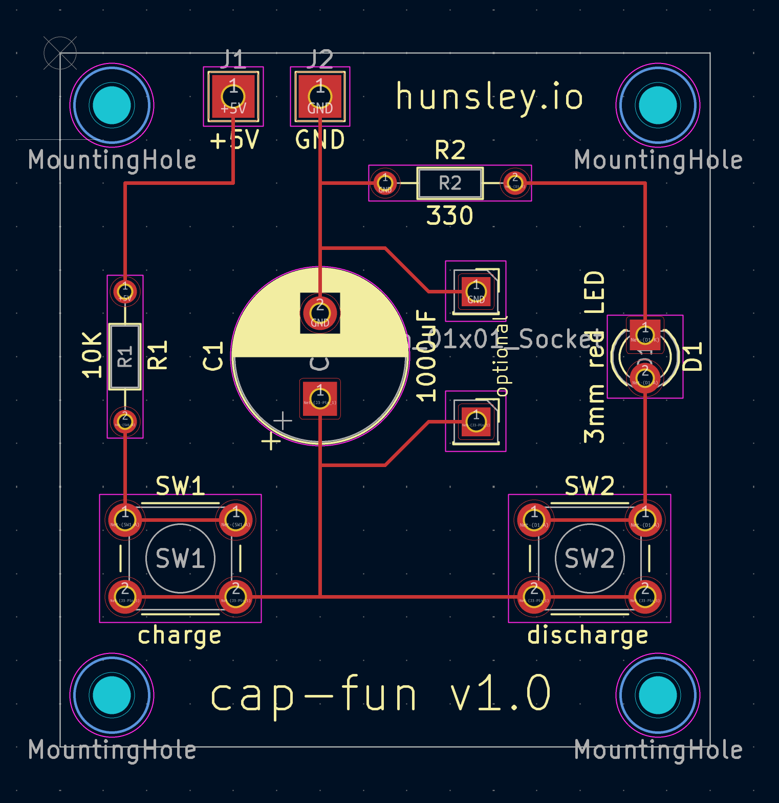
Stand-off holes are provided at the corners.7
I’ve added an optional component hookup for putting something across the capacitor. You could attach a voltmeter to see the voltage of the cap changing, or maybe solder on a bleeder resistor.8 If you put a cap there, its capacitance would be added to the first one, resulting in slower charge and discharge times.
Manually laying down tracks in KCad is very satisfying. I’m sure it’s more annoying once you get past toy projects.
KiCad has a cute 3D viewer and renderer for your board too:

The back side of the board:
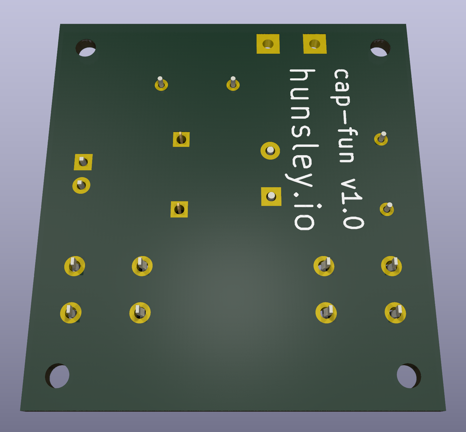
This PCB is quite small: about 4cm across. I might em-biggen it once I see the printed PCB.
Of course, laying out PCBs for educational use is a different beast to designing a PCB to just do something. I’ve laid out the board above in a way that hopefully emphasizes the structure of the circuit: in effect it’s two loops – a charge loop and a discharge loop – with a capacitor in common between them (hence the cap being in the centre of the board, rather than the LED; this is about capacitors, after all).
Varying the power supply
This circuit is marked as using a 3mm red LED and 5V (DC) power. For ease of connecting up a battery, you might want to instead use a 9V battery in a holder with wires for connecting to the +5V/GND header. 9V should be fine but I’d recommend using a regular sized (5mm) blue or white LED with it, as they have a higher forward voltage drop, which means less current will run through the LED.9
| LED colour | Typical forward voltage drop |
|---|---|
| Red | 1.8 - 2.2 V |
| Yellow / Amber | 2.0 - 2.4 V |
| Green | 2.0 - 3.0 V |
| Blue / White | 3.0 - 3.3 V |
Fabrication
I’ve not yet had cap-fun fabricated.10 Popular companies for this are PCBWay and JLCPCB; I’ll get my board made with one of them and post an update.
Honourable mention: KiKit
PCB manufacturers like to print large PCBs for efficiency reasons and so they offer options to get your PCB design(s) repeated across a sheet.
KiKit is a tool that can help you with this aspect by making tabs and cutouts etc. so that your individual PCBs are easier to handle and separate from the sheet, and you get a nicer result. I’m going to try it soon.

Document history
- 2025-06-05: update images to reflect printed PCB v1.0; improve some descriptions
- 2025-05-20: publish
an unconnected cap will eventually leak off its charge, but it might take a while ↩︎
the stable point is a cap voltage corresponding to the cap gaining charge at the same rate as the LED+resistor is taking away charge. This works because the charge/discharge graph of a capacitor is a curve that levels off as time proceeds ↩︎
exercise for the bored: work out charge time for both the charging and discharging action (reminder: \( \tau = RC \) and charge/discharge time is assumed to be \( 5 \tau \). Don’t forget the 1.5V drop over the LED!) ↩︎
answer: it doesn’t matter how charged the cap is to begin with, holding both buttons takes you to the same stable brightness of LED (which relates to the amount of charge in capacitor) ↩︎
answer: once the cap voltage has dropped down to the forward voltage of the LED, no current can flow through the LED ↩︎
answer: use a suitable resistor on its own (no LED). This demonstrates the concept of a bleeder resistor, a safety feature to slowly discharge larger caps when a circuit is powered off ↩︎
the standoff size is 2.2mm (M2 screws); this is smaller than the usual 3.2mm (M3) due to the tiny board size ↩︎
a bleeder resistor is for slowly discharging a capacitor when a circuit isn’t in use, typically for safety with larger caps. For this circuit, a 120kΩ bleeder resistor will discharge cap fully after 10 minutes; to get other discharge times, just scale up or down the 120kΩ, e.g. use 240kΩ to get 20mins ↩︎
reminder: 20mA is considered the max current for many LEDs (before they start blowing); limiting to 15mA might be better for longevity of the LED ↩︎
terminology: fabrication is manufacture of the PCB, whereas assembly is the placing of components on the board ↩︎