Ohmaps: AC/DC walkabout (part 1)
I want to mention the concept of walkabout and then go for a meander with the ohmaps idea. The idea is to eventually look at if the ohmap extends from resistance (DC behaviour circuits) to impedence (AC circuits) in any useful way.
Let’s go walkabout
For quite a lot of years I would go walkabout and not really thinking about what that meant.
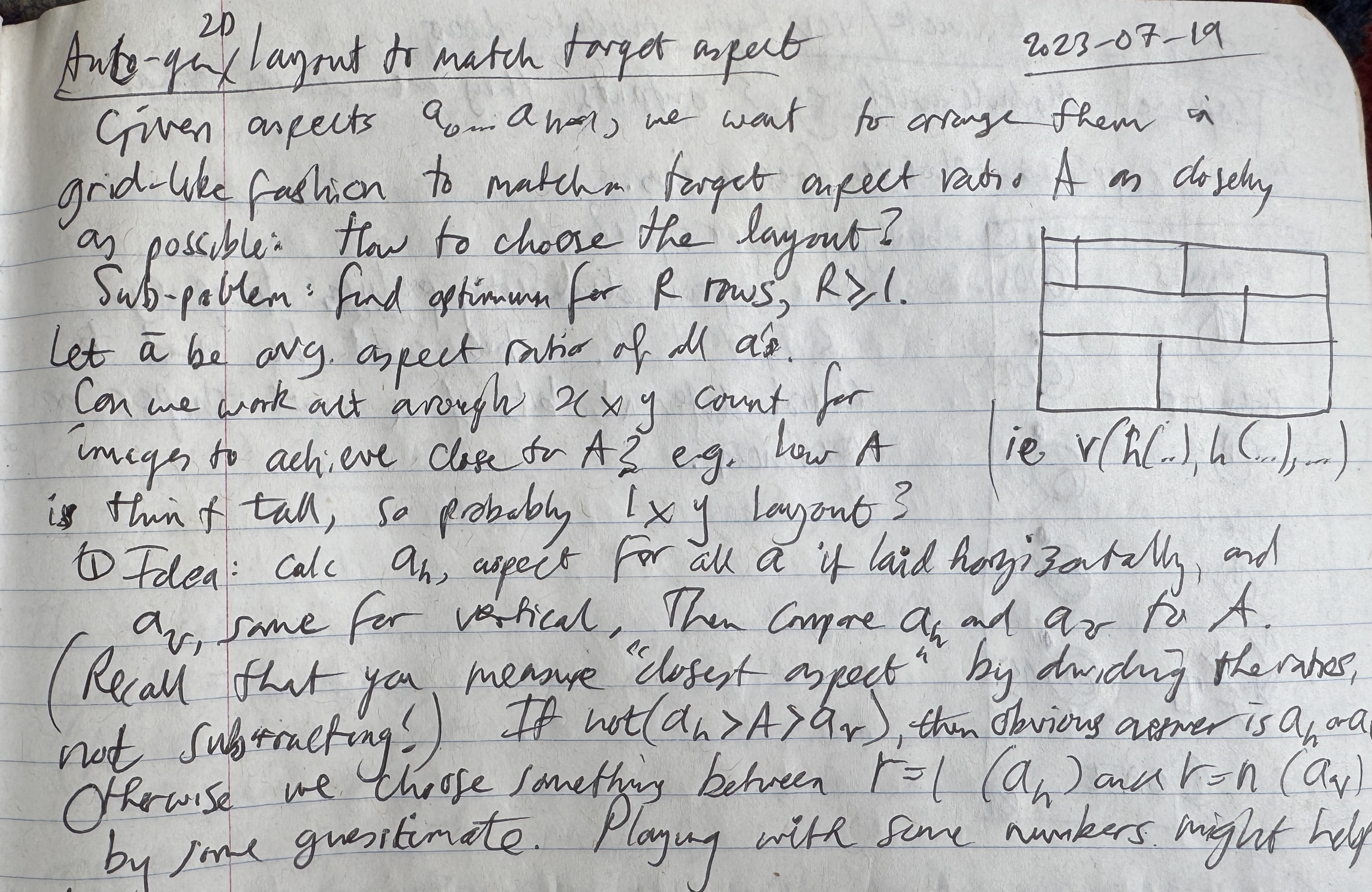
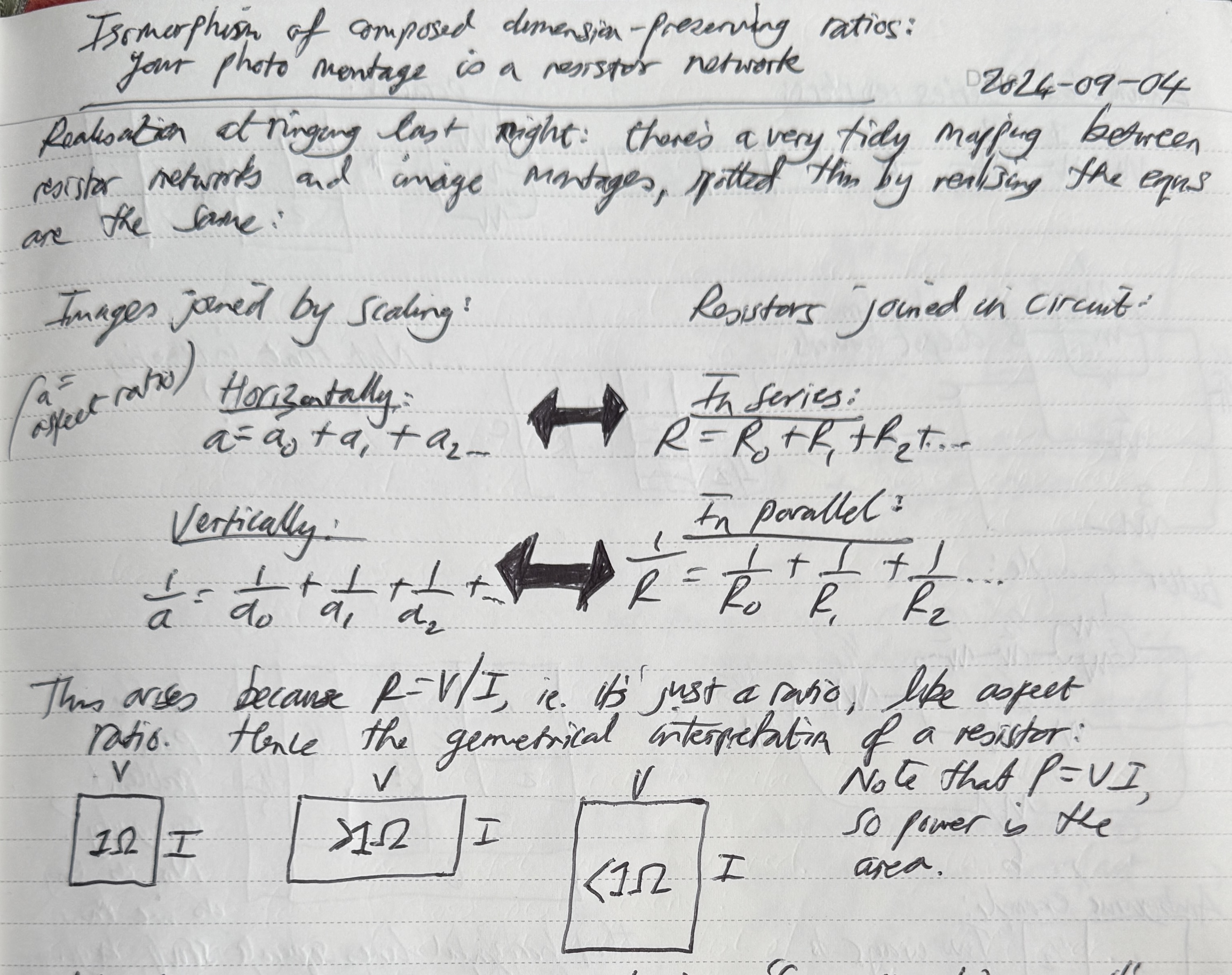
Walkabout is my expression for when I’m thinking about one thing and then I go off in some other interesting direction or I try to generalise something. The original ohmap idea is a good example: I was just sketching some trivial code for building image montages, and I later spotted the simple mapping to resistor networks.
I love this sort of wandering for the surprising places it can take you. Just the act of playing can be a catalyst in areas of creativity or realisation.1
If you go walkabout, you don’t necessarily find anything interesting at the end. But the act of exploring a bit and looking around can be beneficial. If you learned something on the way, it’s a win.
Walkies with ohmaps
So an ohmap is a picture of how resistance hangs together in a network. But it only deals with DC circuits, the realm of purely resistive circuits.2
What about impedence, which takes the idea of resistance into the realm of AC? Could the ohmap idea extend to impedence in any useful way?
To explore, we need to understand impedence, and then try to take the idea forward. And at this point I have no idea how workable impedance ohmaps might be.
Resistance is fertile
Resistance is one of the components of impedence:
Reactance is the tendency of some electrical components to resist the flow of AC. Typically these components have capacitance or inductance.
The higher the reactance, the less current will flow for a given voltage, similar to resistance.
Expressing impedence as an equation:
$$ Z = R + jX $$Reminder: \( j \) is how electrical engineers write \( i \), the square root of \( -1 \).
So impedence is a complex number, and reactance is an imaginary number (a real multiple of \( j \)).
That complex number represents a phasor (more on this below).
Here’s some example impedence values, just to hammer home the complex number bit:
$$ \begin{aligned} 2 & \quad \textrm{ (a resistor) } \\ \\ -j & \quad \textrm{(a capacitor)} \\ \\ 2.5 + 3j & \quad \textrm{(a resistor and an inductor)} \end{aligned} $$We’re not in Kansas any more, Dorothy.3
Get this house off me
There’s an equation very similar to \( R = V / I \) for calculating impedence (Z):
$$ Z = \frac{V}{I} $$However, the V and I used in the definition of \( Z \) above are phasors (complex numbers), not just scalars like 10V or 2A.
This similarity is somewhat encouraging for the idea of extending ohmaps, because the classic \( R = V / I \) is a fundamental part of the ohmaps idea.
To be accurate, it’s not just a similarity: they’re representing the same thing. The familiar resistance equation is just the special case for DC behaviour circuits where the impedance is a real value (no imaginary part).
Getting a good handle on all this is helpful for any attempt to extend ohmaps into AC.
Tell me about phasors
Phasors are extremely useful. And they have some subtleties that are worth nosing out.
A phasor is a complex number. The polar coordinate interpretation of that complex number represents a sinusoidal wave: the radius is the wave’s magnitude and the angle is the wave’s phase offset.
A phasor can be written as the raw complex number or in polar form. Some examples showing the equivelant forms:
$$ \begin{aligned} 0 &= 0 \angle 0^\circ \\ 1 &= 1 \angle 0^\circ \\ j &= 1 \angle 90^\circ \\ -2 &= 2 \angle 180^\circ \\ 1 + j &= \sqrt{2} \: \angle 45^\circ \\ 3 - 4j &= 5 \angle\! -\!45^\circ \end{aligned} $$In general:
$$ r \angle \theta ^\circ = r(\cos \theta + j \sin \theta) $$We could also write it in Euler form, which says the same thing:4
$$ r \angle \theta ^\circ = re^{j \theta} $$The phase offset is usually written in degrees, typically having a value from \( -180^\circ \) to \( 180^\circ \).
Offset from what though? Well, it’s not specified!
Note also the lack of any concept of frequency (or wavelength) in a phasor.
It feels like we’re missing something then?
This insecure feeling resolves with this realisation:
When you are working with multiple phasor values, and combining them, they are assumed to all have angle offsets relative to some common (unspecified) point, and to all relate to the same wave frequency.
It’s worth sitting with the above until it really sinks in.
This realisation tells us that it doesn’t make any sense to try to combine or compare phasors that don’t share these two ‘reference points’ (offset base and wave frequency).
Here comes the subtlety:
A phasor doesn’t explicitly contain the frequency of the wave it relates to, but it does encode it!
This is the power of phasors: simple but expressive for what they do; they embed some details already accounted for without having to be overly explicit.
A practical example: suppose you have a circuit containing a capacitor and an inductor. When you calculate their impedences, you use the same \( \omega \) in both calculations, which is the angular frequency of your AC power (i.e. radians per second swept out): \( \omega = 2 \pi f \)
The resulting impedences don’t explicitly record the \( \omega \) value, but it’s encoded in both, so the phasor values can be sensibly combined to calculate their series impedence (by summing the impedences). And the resulting phasor is necessarily only useful for the same frequency wave: your AC source.
Walkies will continue in part 2, where we’ll build up further understanding of impedance
one of my favourite examples of play as catalyst is when Feynman was playing with the physics of spinning plates. This play re-ignited his interest in physics during a difficult period. He’d go on to work on the path integral formulation of quantum mechanics, QED, etc. ↩︎
it’s worth noting that AC circuits can behave like DC circuits (purely resistive) at low enough frequencies; a boundary sometimes quoted for this is 10Hz ↩︎
apropos of nothing, pronounciation aside, does anyone else mentally translate Arkansas into the reciprocal of Kansas? ↩︎
Euler form is cool though, as it gives a tip towards de Moivre and hence the geometric interpretation of impedance products. De Moivre tells us: \( (e^{i\theta})^n = e^{in\theta} \) ↩︎